Measuring for Driveshafts
Here you will find images to assist you in properly measuring your vehicle or auxiliary equipment for a new or replacement driveshaft(s). Once you understand where to measure from and two, getting it right the first time is quite simple. There are but two rules not to be deviated from: be sure of your measurement. Do it twice if you have any question about the first. A driveshaft is made-to-order and there is very little room for error in measurements. Get it right the first time. And secondly, all vehicular measurements must be taken with the vehicles’ suspension at ride height. The suspension compresses and extends, changing the operational distance the shaft must cover. Play by these rules and your new driveshaft will fit perfectly. The parts in the illustrations may not look exactly like your parts but represent a part type you should be able to match to yours.
FIRST, SOME DEFINITIONS….
There are a few defined points of measurement for any driveshaft.
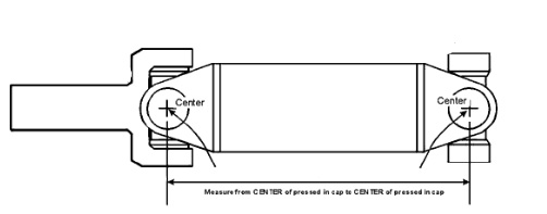
Centerline: the center of the universal joint cap in a slip yoke or end yoke and abbreviated as CL.
Centerline CB: the centerline of a carrier bearing or, on a vehicle, the center of the mounting bolt hole on the bearing bracket and abbreviated as CL/CB.
End of Shaft: the tip of an input or output shaft, abbreviated as EOS
Face of Flange: the flat face of a flange, be it a flange yoke or companion flange and abbreviated as FF.
Half Round Face: the machined flat surface of a strap or u-bolt style end yoke where the strap lies and abbreviated as HRF.
Inboard and Outboard: refers to position, either between universal joints or outside them, commonly with regard to a slip yoke.
ONE PIECE DRIVESHAFTS
Found in many passenger cars and most light trucks, using various series of universal joints, the single piece shaft is quite common and very easy to measure. Nearly all of them are as pictured below: an outboard transmission slip yoke at the business end with either an open u-joint or a flange yoke (not shown) a the rear. This style driveshaft may be steel or aluminum and we build and repair either. An open rear u-joint indicates an end yoke on the pinion, a flange yoke mates with a companion flange on the pinion. Measure for either as shown. In our shop, this style of driveshaft is known as a style #1 shaft. There are also style #2 one-piece driveshafts having inboard slip yokes, measured in the same way.
With transmission slip yoke 0.50-0.75″ off bottom measure from CL-to-CL (or CL-to-FF). The half inch or so up front allows the shaft to change length as the suspension functions. A #2 shaft is measured CL – CL as well with the movement of the shaft being inboard rather than outboard.

TWO and MULTI-PIECE DRIVESHAFTS
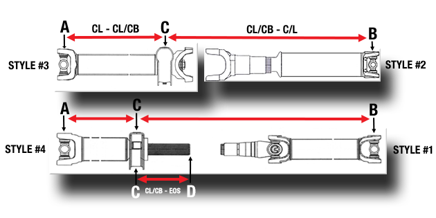
Not as common as they once were due to the advent of aluminum in shaft building, two piece driveshafts are still found in some longer wheelbase pickup trucks, step vans and the like and are still the way things are done in the heavy truck world. All must be measured accurately for proper fit and operation, particularly front carrier bearing shafts. Below are shown the possible configurations of two- piece driveshafts.
In our shop, a carrier bearing shaft with a fixed end yoke behind the bearing is known as a #3 shaft and mates with a #2 with an inboard slip yoke. A carrier shaft with a splined stub through the bearing is a #4 and mates with a #1 with an outboard slip yoke.
In both configurations the carrier bearing shaft is measured CL – CL/CB (or bracket bolt hole on vehicle), end yoke or flange to bearing center. The rear shaft is measured CL/CB – CL, bearing center to pinion yoke (or FF of companion flange).
If you are measuring for a rear shaft only on a #4 style bearing shaft you will need to include the CL/CB – EOS dimension as well, center of bearing to end of the bearing stub. This informs which slip yoke to use on the front of the new rear shaft. We’ll also need to know the outside diameter and spline count of this bearing stub.
Some very long wheelbase applications have two or more carrier bearing shafts and each of these are measured CL/CB – CL/CB, centerline of the first bearing to the centerline of the next. All carrier bearing shaft measurements in particular must be very accurate as the mounting points (end yoke or flange-to-bearing bracket) are fixed points that are immoveable. With a slip style shaft there is room for a bit of error but not the case for bearing shafts. Measure accurately.

AUXILIARY EQUIPMENT DRIVESHAFTS
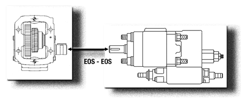
Driveshafts for auxiliary equipment are measured a bit differently from vehicular shafts. It might be a hydraulic pump (as shown), rotary screw compressor, product pump or something else, but all are measured in the same manner: tip of shaft of the driving unit to tip of shaft of the driven unit, known as a tip-to-tip or EOS – EOS measurement. In addition, measure the shafts sizes and keyways of both shafts (OD and spline count in the case of a splined shaft). A power take-off moves with engine torque requiring all such driveshafts be a style #2 shaft to allow for movement. It is always prudent to install an auxiliary driveshaft with the slip end at the power take-off: in the event of failure of the shaft only the slip yoke is left rotating, minimizing collateral damage. An auxiliary driveshaft may be two or more pieces if the distance to cover is great. Such shafts may be of tubular build or solid shaft, depending upon the distance to be covered and speed required. Please contact us prior to installing any auxiliary equipment for information on your best options.

ON LENGTH, SPEED and ANGLES
Though not given much thought in most circles, driveshaft overall lengths, the angles they are installed at and the speeds they must run are all critical elements of specifying a shaft correctly. Failure to take all of these factors into account can result in poor operational performance and potential disaster. Such things are quite technical in application but with literally tens of decades of experience, how these factors interact are second nature to our sales staff. Please call us with any questions you may have when laying out a rig up involving auxiliary equipment requiring driveshafts.
For those that enjoy technical rabbit holes, please refer to the Spicer 3311 catalog linked on our Technical page.
