Power Take Off Tech
These parts lists and manuals are quite large PDF files and may load slowly.
Patience, grasshopper.
CHELSEA POWER TAKE-OFF PARTS LISTS
249 Parts List
270 Parts List
272-282 Parts List
277-278 Parts List
280 Parts List
340 Parts List
442-489 Parts List
823 Parts List
852 Parts List
863 Parts List
880 Parts List
890 Parts List
CHELSEA INSTALLATION GUIDES
249 Install Guide
230/270/272/282/852 Install Guide
277/278/280/859/870 Install Guide
890 Series Install Guide
MUNCIE POWER TAKE-OFF PARTS LISTS
TG Parts List
CS24 Parts List
RL Parts List
SH Parts List
82 Parts List (prior to 2017)
82 Parts List (2017+)
83 Parts List
MUNCIE INSTALLATION GUIDES
Driveshaft Tech
Measuring for Driveshafts An illustrated how-to.
Spicer Series Torque Ratings Use the right parts for the job.
Dana/Spicer Media Library All things Dana/Spicer…..all things.
Spicer IJ900 Catalog Industrial driveshaft specifications.
Spicer DSIG3311 Technical drivetrain setup guide.
Spicer U330 Auxiliary driveshafts and parts.
Hydraulic Tech
Gear Pump Identification Chart Measurements to identify your pump.
Hydraulic Troubleshooting Chart Conditions and possible solutions.
Permco’s Gemini Pump for Trailers and Live Floors Dual duty dump pump.
GEAR PUMP BASICS
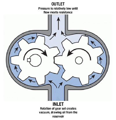
Hydraulic gear pump design has remained quite the same, aside from material advances, for centuries: a gear set rotating within an iron or aluminum housing producing oil flow at pressure to do work. The pumps’ ability to deliver pressure efficiently depends entirely on tolerances between the gear teeth and the gear body, and the thrust plates on the top and bottom of the gear set. These parts are fitted together to create what amounts to a sealed space that only allows oil to be pushed to the pump outlet and nowhere else. Time takes its’ toll, however.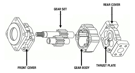
Pressure from the outlet side of the pump creates force on the gear set, pushing it toward the inlet side, and the steel gear teeth slowly eat away the iron gear body on this side. This creates space where there was none and the pump begins to lose efficiency. In bearing design pumps, the gear journals are supported by roller bearings. In bushing designs, the journals run in bronze alloy bushings and have a tighter tolerance. This accounts for the higher pressure ratings of bushing designs. Thrust plates in both designs are machined to allow high pressure oil onto their backs, forcing them down onto the gear set, contributing to sealing the space within the gear body. But thrust plates slowly wear away with the turning of the gears. The fine metal cut away from the gear body and thrust plates gets suspended in the oil and acts as an abrasive. Extended duty cycles generate heat in a system and in many circumstances an oil cooler is required to avoid heat damage to pump components.
To extend the life of your gear pump do not exceed the manufacturers’ pressure rating, keep your oil free of contaminants with an in-line filter and do not overheat the system. Using the right components for the job is the best way to ensure long life, and the best way to get the right components is by consulting the experts first.
HYDRAULIC PLUMBING DIAGRAMS
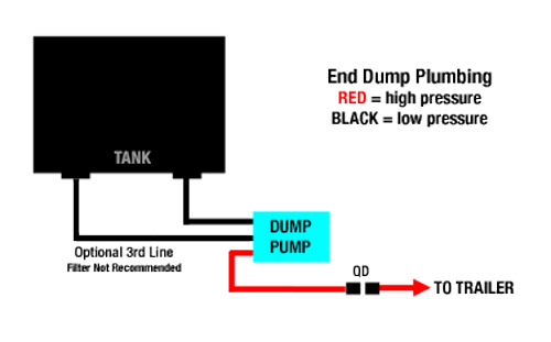
Two and Three Line End Dump
In a two line system, one line serves as supply and return, the other the pressure line to the cylinder. A three line system makes use of the pumps’ return port to minimize potential heat problems that can be associated with a two line system. With either, it is important to purge air from the supply side line before operation. The pump will not pull an air pocket out of the line and will be “running dry” with no oil supply – a sure way to damage the pump. Please note that a sleeve must be placed in the inlet port of the pump in order to make the return port functional. This sleeve may or may not be included with a new pump, depending on manufacturer. Please let us know if you are replacing a pump in a three line system.
We do not recommend a filter in this return line due to the volume of return flow.
Hydraulically Driven Auxiliary Equipment
Blowers, rotary screw compressors, winches and other equipment may be truck mounted and driven hydraulically by incorporating a motor spool control valve and motor into the system. Control valves may be manual or air operated. The output of the motor is most often direct-coupled to the input of the driven equipment with a chain coupler, lovejoy joint or adapter specific to the equipment. A filter in the return line is optional but recommended, as is an in-line oil cooler for long duty cycles. Specification of such systems is detailed and critical. All components must be matched to the specific requirements of the driven unit. Listed here are a few examples of pump-motor combinations for various rig ups.
Product Pump: 20GPM@<2000psi with 6.0-6.2cir motor = 700-750RPM for product pump
30K Winch: 15-20GPM@2000psi with 24cir motor = 300-400RPM for winch shaft
45K Winch: 25-30GPM@2500psi with 29-30cir motor = 300-400RPM for winch shaft
Please contact our sales staff for expert evaluation and specification of your particular needs.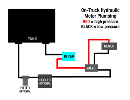
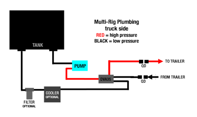
Truck Mounted Hydraulics for Trailers
Some trucks are rigged to deliver hydraulic power to a trailer and often the same truck will haul different trailers: end dumps, low boys, roll offs, live floors, vacuum trailers and others. Some trailers may well have a hydraulic control valve of its’ own, only requiring a source of oil to accomplish the task. This multi-rig plumbing illustration can supply oil under pressure for such trailers. The DVA35 control valve is single acting and equipped with quick disconnect fittings on both the pressure and return side (second return port), allowing for simple QD connections to trailers. Flow and pressure requirements vary.